

I’ve been reading about Magic Mirrors for several years and the ever evolving functionality they provide. Use case was simple to justify the expense of creating a magic mirror, but finding the time was the primary issue. Well, extra time finally came about and, after a few higher priority projects, time was still available for a Magic Mirror.
Googling and youtube have many how-to’s to create a Magic Mirror and there are a few different options available. I latched on MagicMirror because it is open source, contains several good built-in modules, and has a decent sized module developer community.
In my case, I had an extra 23″ monitor and raspberry pi 3b+ sitting in basement storage which I pulled out to test the electronic piece of the puzzle. After installing Rasbian with Desktop on the Raspberry Pi and getting it connected to WiFi, installing MagicMirror was a simple one line.
Over a few weeks, I added, removed, and adjusted modules until I was seeing exactly what I found useful. The nice thing about MagicMirror is the developer community and how many modules have been created that fit exactly what I was looking to accomplish. I then began gathering all the components.
- Monitor
- Raspberry Pi 3b+
- Smart Glass
- Wood
- 4 L brackets
- HDMI cable
- DVI to HDMI right angle adapter
- AC barrel plug right angle adapter
With the display now having what I wanted to see, the next step was thinning the monitor and build a display case that would look nice hanging on the wall. Thinning the monitor by removing the plastic from the monitor and disconnecting the controller board was relatively easy. I was able to measure the monitor and purchase Smart Mirror Glass from Two Way Mirrors. The glass was the largest out-of-pocket expenditure if I don’t include the monitors and raspberry pis I already had. You’ll see why I use plural for those later.
There are several how-to’s floating around the web that will show how to create the wall mount for the magic mirror. I was fortunate because we have a wood working guru, Mike K., as a member of OMG. He was able to quickly design and explain the case to me. He then helped me with the tools necessary to make the cuts. The smart glass and monitor fit in the rabbit cut to hold them secure. We used a router for those cuts along with the back braces. We had the case cut and ready for staining in just a few hours. Mike K. is owed a great deal for helping me make the magic mirror look aesthetically pleasing and not an obvious hack job.


At this point I was getting fairly excited about the finished product and how quickly the case came together. I found out that staining takes a while to do well and has decent wait times between each side to let the stain thoroughly dry. Once the wood was stained, then assembly began and went fairly quickly. I made sure to clean the monitor screen and glass and then wore gloves so that I wouldn’t leave finger prints during assembly. I had no interest in taking it apart once assembled.


I had tested the monitor and raspberry pi throughout the this process to verify that it continued to work. After assembling the glass, monitor, and frame, I tested it again successfully before securing the frame beyond the wood glue. The setup worked great and I left for the day.
The next day I returned and tested the setup again to make sure the electronics were working okay. Again, successful so I proceeded to add the L brackets to the inside of the frame to finish the assembly. The L brackets were centered between both edges of wood and did not touch the electronics anywhere. I then tested the electronics again and the monitor had lines through 2/3 of the screen. I switch DVI and VGA adapters, HDMI cables, modified the config.txt file on the raspberry pi, but nothing worked.
Unfortunately, I had to take the frame apart and switch it out with an identical monition I had at home. The original monitor I was going to use had been pinched to tightly in the corner where a ribbon cable connects tot he monitor. I thought there was enough room and didn’t pull the table on the ribbon cable back enough to realize exactly where it connected and that it was a delicate spot. Before reassembling, I carved out some additional space in the frame. Once reassembled fully, the second monitor worked great and continued to work great for each test.
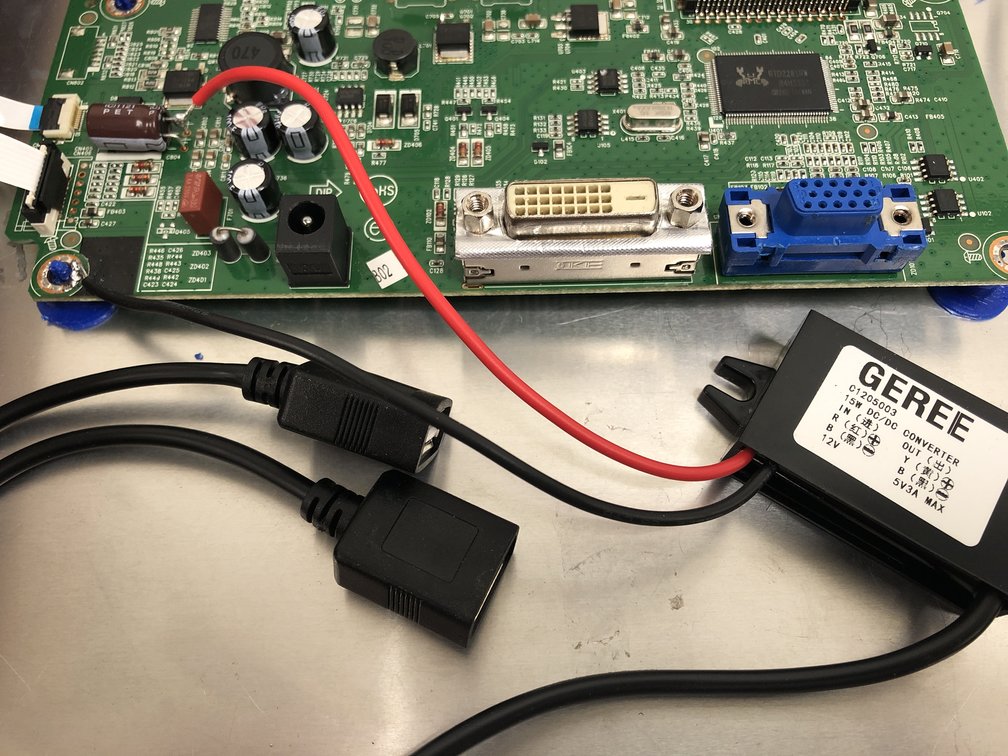
My goal was to reduce the number of power cables on the inside of the frame. The idea being there would be less heat because of fewer power adapters, more space for air flow, and overall weight would be less. Michael A. had helped me solder a couple weeks previously and we looked at options. The monitor controller board would be used with a step down adapter with usb ports to feed the raspberry pi power. Using this method, there would only be the need for the monitor AC cord to be fed into the back of the frame.
This is where I hit my second problem of the project. Using a multimeter, we found a 12v transistor that would gives us the positive power and we would attached the ground to the screw location of the board. I then soldered the step down and put all the cables back on the monitor controller board and powered it up. Everything looked good so far so I removed the power from the controller board. The moment of truth had come so I plugged the raspberry pi in one of the USB ports from the step down and powered it all up. The screen flickered, I saw smoke coming from the point where the usb power connects to the raspberry pi, and quickly pulled the power plug. Unfortunately, the raspberry pi does nothing more than get extremely hot when plugged in to the usual power adapters I use. Oh, and that 12v transistor on a retest with the multimeter generated 48v. The solder connections messed up the throughput and once disconnected the transistor was a steady 12v.
In the end, Kevin helped me go the easier route by adding all the power cables in the case. All boots and works as expected and hangs on the wall in my office nicely.


