
Recently I discovered that my doorbell has become unreliable. The UPS guy never wants to wait around, and sometimes he takes the packages with him, so I had to do something about this problem. I picked up a new bell at the hardware store for a couple bucks, but it’s a cheap plastic model, where the original is a nice heavy metal model with a light in it.
I took apart the old one to see if I could swap parts to reuse the nicer one, and found that the only part that was really a problem was the button, which has degraded on the side facing the afternoon sun.
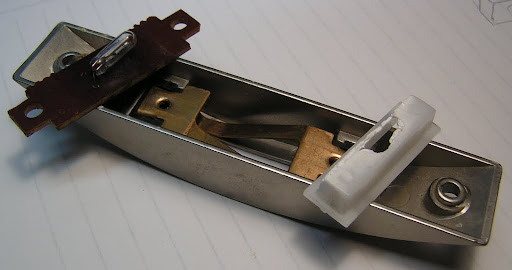
Fortunately the new one is almost exactly the same size, so I swapped it in and had a like-new repair. Cool, 5 minutes and the job was done.
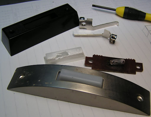
Of course, as soon as I reconnected the wires the little light bulb burned out. It’s been running continuously for 5 years now, so I guess that isn’t too bad a lifetime, but I’d like the button to be lit, so I’ll need to get that little guy out of there and find a replacement.

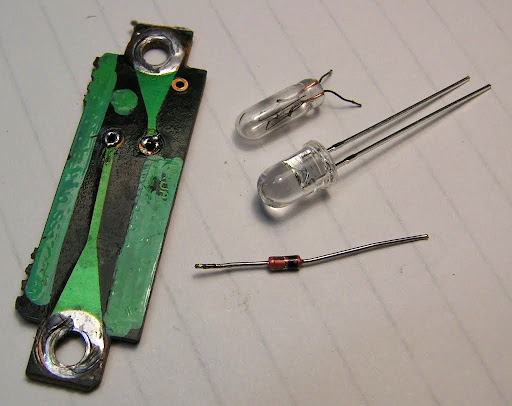
I’d probably have to spend $15 on a new lighted switch to get one of those little 20VAC bulbs, so I’ll be looking for something else. Twenty volts is a little low for neon bulbs and electroluminescent wire or film, so I guess it’ll have to be an LED. Fortunately I’ve got a ton of those. Red would be neat, but maybe a little boring. I have a bunch of IR LED’s and some luminescent powder, so I could coat the inside of the button and make it glow, but I’ll probably have to replace it again in a few years, and I don’t want to have to reapply the glow powder. So I think I’ll go with one of the blue LEDs I had left over from my binary clock project.
The LED will need a diode to block half the AC voltage and a resistor to limit the current. I used 33mA for the clock, and that’s plenty bright for this, so I found an ~800 ohm resistor for this.
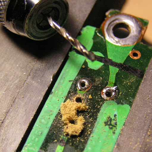
There isn’t much space in the doorbell, so I marked where the circuit board did not lay on top of the metal contacts, connected the resistor and diode and laid them out to see where I’d need new holes for the leads.
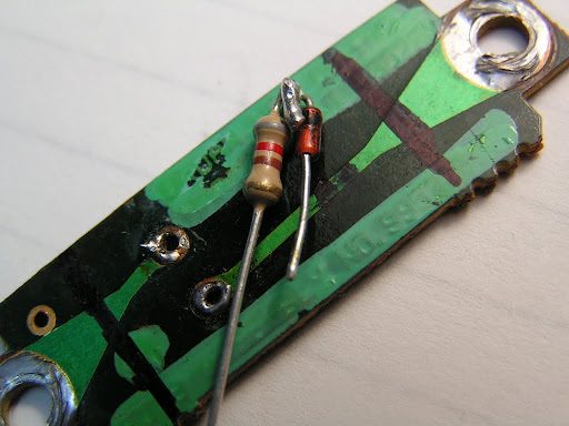
Looks like it will fit without much trouble. There is just enough room between the PCB and the wall to avoid squashing the resistor. I marked the trace where the new holes will go and drilled them out.
Then cut the trace between the new holes.

A little work with a needle file to make some new pads around the holes…

And I can solder in the new components.

Next the LED goes in, but first I lopped off the lens with the dremel to turn the end of the LED into a diffuser. There isn’t enough room in the switch body to stand it up, and the beam is too narrow for that anyway.

Before I reassembled the switch I took the chance to bend the contacts into a higher arc so that the button only has to be pushed about 2mm to make contact. It was set for more like 3mm, which put the button almost inside the switch body, which was contributing to the difficulty of getting it to work.
I put it back together and hooked it up, and it’s working as planned:

A neat improvement on this would be to replace the factory board with a custom board with an ATtiny13 and a couple SMT RGB LEDs so that the button could cycle through a set of colors. It would reset when the switch is pressed, so the startup code could do a neat flash of colors to indicate that it had been pressed before returning to the usual slow color cycle.
Great post, Dave! I liked how you started off replacing a faulty doorbell and ended up making the old one better than ever instead. 🙂 Cutting the LED to help it diffuse the light was a nice touch as well.
Thanks. I had to come up with a way to make the project take longer, or I’d have been stuck doing the brakes on the car 😀
Unfortunately, it looks like I’ll need to fix it again, the LED has gone out. I suspect either the peak current was too much for the LED, or my junk box diode wasn’t rated for that voltage.
I had the same need and my circuit and implementation were very similar including grinding a diagonal on the LED to direct more light to the button. The initial performance was so bright, it was visible from several blocks away. My final results were also the same, the LED got dimmer over time until it went out.
One thought is back EMF from the doorbell coil eventually destroyed the LED, the other is that the LED was driven too hard. The next version I’m thinking of would have a full-wave bridge to get 60Hz instead of 30Hz, install a pair of zener diodes to provide protection to the LED, and a larger current-limiting resistor.
very cool project.. I have a doorbell light out and couldn’t find a neon replacement, I will follow your instructions and go LED, Thanks!
I used a warm white 5050 SMD LED, taken apart a T10 automotive bulb to get 5 modules, each them has 3 chips and the little PCB have them wired in series so the Vf is about 9V, along with a 220 ohm resistor (what I had on hand) for roughly 20mA output with 12v DC, the 1/2W is a bit too big, a 1/8 should have been sufficient and fit better. I couldn’t stand the transformer buzzing away and didn’t want to see the LED light flickering since it will only see half of the sine wave (25/30hz), if using on AC, one should add another diode to protect the LED from the reverse polarity.
[img]https://i.imgur.com/c4vrLs0.jpg[/img]
[img]https://i.imgur.com/X3FSRTd.jpg[/img]